Nozzle Back-Pressure, Speed and Pressure Advance
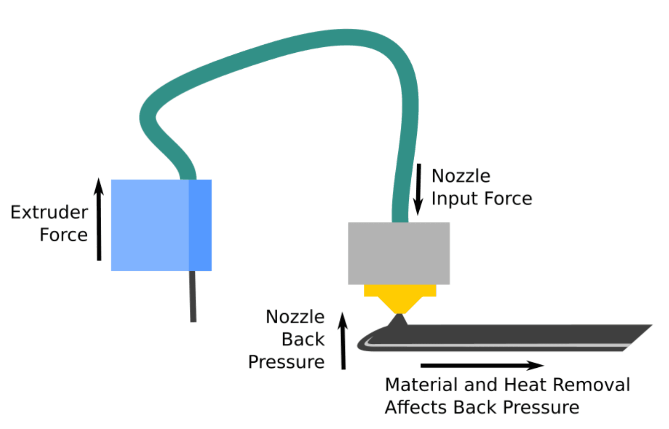
The standard approach to pressure advance assumes that the rate at which filament exits the nozzle is determined by the force provided by the extruder motor, and that other forces are negligible or constant. One of the forces assumed to be constant is the “back pressure” - the reactive force caused by trying to squeeze plastic through the gap below the nozzle. Although this is mostly constant during straight lines at constant speed it changes during turns and as a function of layer thickness, extrusion width, and speed. Most of these things are constant during a given print run, but will potentially change between them. The question is then, what is the effect of back pressure on the relationship between extruder force and print width?
In previous posts [1,2,3] we have shown some different ways of measuring the pressure advance constant. The measurements we have made kept the speed across the bed the same, and varied the amount of extrusion. Taking measurements this way makes it easier to interpret and analyse the data, but the situation isn’t completely representative of normal printer operation, as generally speaking, prints will be done with the aim of having a constant extrusion track width most of the time.
We can expect this difference from normal printing to have some kind of effect on the estimated pressure advance constant, because the material outside the nozzle will resist the extrusion of new material, and moving material away from the nozzle will also take heat away and thin out the track making it cool quicker. The size of each of these effects is unclear.
So let’s have a go at quantifying this effect; looking at a range of print speeds and sampling a 2D parameter space of surface/bed speed and extrusion rate.
The Tests
In all the tests we looked at 75% step changes in extrusion speed and used our optical measuring system to measure the resulting track widths in three different conditions: one where the surface speed matches the extrusion rate (constant target line width), one where the surface speed doesn’t change (like in our previous experiments), and one somewhere in between.
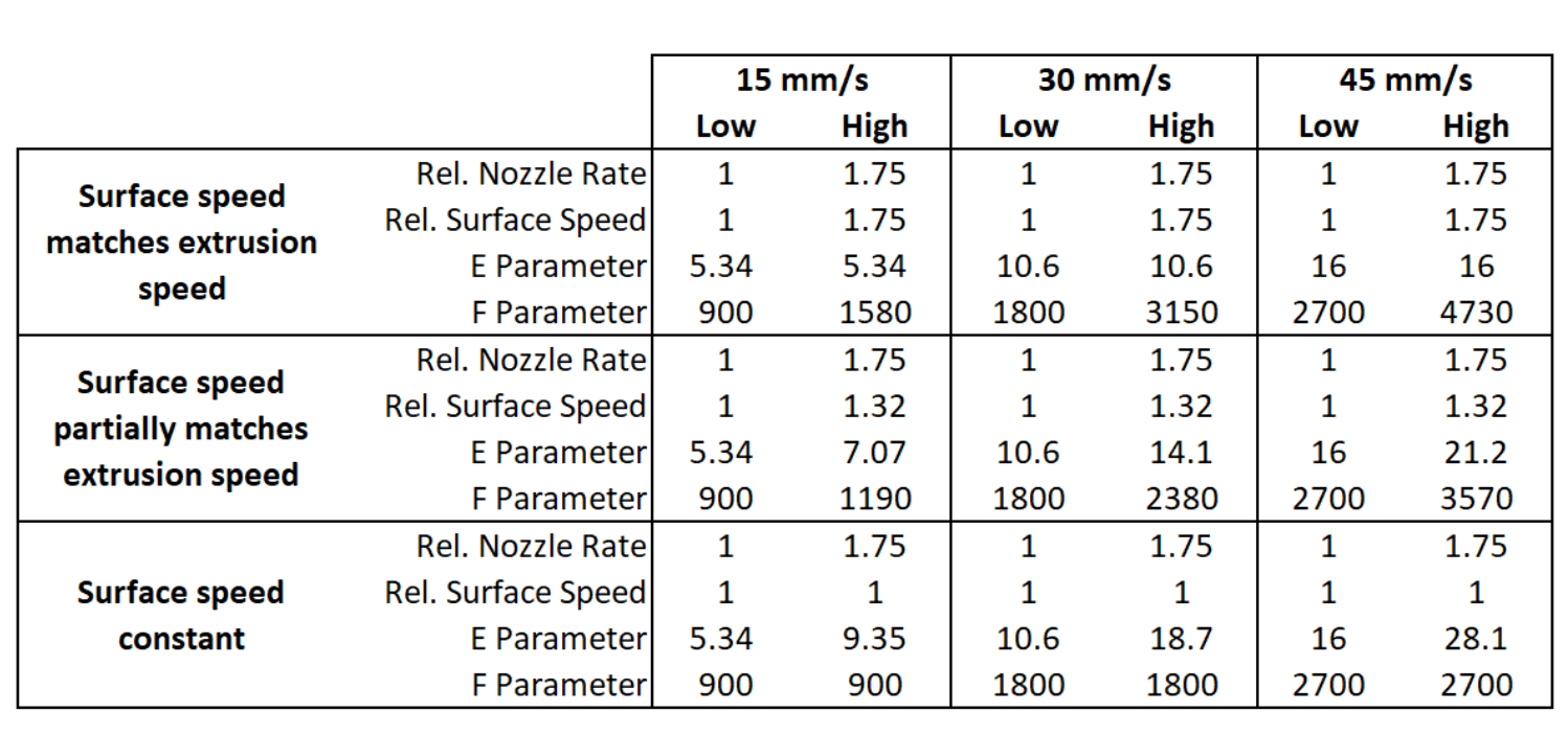
The following is a table summarising the tests we ran. We used base speeds of 15, 30 and 45 mm/s, meaning step changes between 15 and 26.25mm/s, 30 and 52.5mm/s, and 45 and 78.75mm/s. The E and F parameters are those specified in the gcode for the test. E is the amount extruded in a move (mm of filament to extrude), and F is the speed the move is executed (mm of distance travelled / min)
Measurements
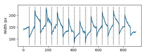
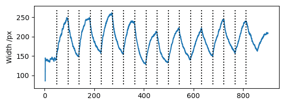
Below are the measured track width for these tests at 15mm/s. The constant surface speed tests look like the ones we have done before, and the matched surface speed tests look like the predictions made in our first post on this topic. When there is a step change in extrusion, the width jumps and settles down over time. When target surface and extrusion rates are the same, they settle down to the same value (ignoring some systematic noise). When the surface rate stays constant, the width settles towards different values for low and high extrusion rates.
Surface/bed speed matches extrusion rate
Faster surface/bed speed, but slower than matched
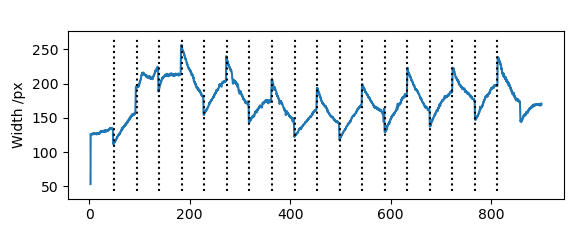
Constant surface/bed speed
Converting this data into extrusion rate data is not too difficult. As track width is determined by the ratio at which filament is extruded to the surface speed, one can simply multiply the width by the surface speed to get something proportional to the extrusion rate. Once we have done that we can fit an exponential curve like we have before, and use the exponent to give us the corresponding pressure advance constant.
Finally, we can get a graph like this:
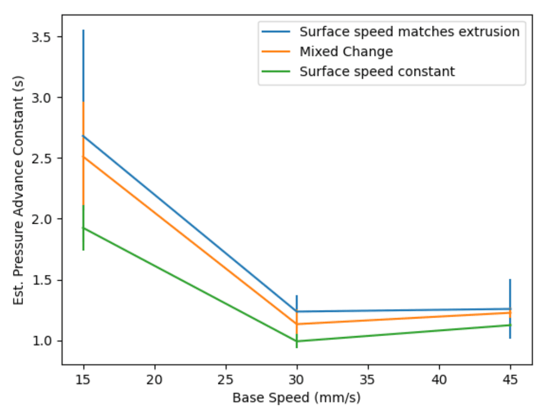
This shows that the pressure advance constant estimate is much higher at lower speeds, and that the relative movement of the bed and extruder matter more at lower speeds.
Pressure Advance
Why does the pressure advance constant differ more at lower speeds? Lower speeds mean lower extruder forces in general, so an obvious hypothesis is that the back pressure is relatively small and it starts to become outweighed by the extruder force at higher speeds.
Another hypothesis would be that the model of extrusion used in pressure advance, which leads to the idea of a pressure advance constant, is not good enough to capture what is happening. For example, the pressure advance model assumes linear behaviour of the material.
If either of these hypotheses are the case, a better pressure advance model would be advantageous.
Some Practical Outcomes
The speeds where backpressure makes a big difference to the estimated pressure advance constant are pretty slow compared to a typical print, but there is some difference even at the higher speeds. When choosing a pressure advance constant, it is probably worth calibrating it again if your print settings change in a way that will affect back pressure, such as using a different print width or height. We may explore automating this change in future firmware, if it can be successfully measured.