
Duet3d Scanning Z Probe
No bed is perfectly flat. There are many methods for characterising the bed surface prior to printing to allow the firmware to compensate for variations in z height in the bed. In RepRapFirmware we call this Mesh Bed Compensation. It is distinct from Bed Levelling, as it assumes the bed is as level as the user or other processes can get it, before a mesh of the bed surface is built. In general, machines use the same method to scan the bed as to probe the bed to set the Z height, for example using a switch, nozzle contact probe, BL touch, or other z probe to measure the Z height at each point in the mesh. For a relatively fine mesh (e.g ~400 points) that is a very slow process (400+ points @ 1+ seconds per probe = 6+ minutes). As this needs to be done with the bed at printing temperature, with the intended printing surface, it would ideally be done per print, as with removable build plates, the surface is different each time.
A potential solution to this is a “Scanning Z Probe” which uses a property that changes by bed distance, without having to move the probe in Z to quickly scan the bed surface. There are multiple potential methods of doing this, depending on the bed surface. We first explored using induction as outlined in a previous blog post. The obvious limitation is this is limited to metal bed surfaces - happily many popular bed surfaces are PEI or other compound coated flexible steel so a good target for induction based measurement.
We investigated an off the shelf solution using a LDC1612 breakout board in a previous blog post. This post will outline our integrated CAN-FD connected solution for machines running RepRapFirmware.
Duet3D Scanning Z Probe
We have developed a CAN-FD connected Scanning Z Probe board that uses an on board microprocessor to interface with the scanning IC and send the results over our CAN -FD distributed control bus to the mainboard. Integrating and mounting a Duet 3 Scanning Z Probe is easy, we deliberately separated the processing board from the coil that is used as a sensor using a Flat Flexible Cable. That allows for freedom of mounting of the sensing board, as only the coil needs to be next to the nozzle and close to the bed.
 The Duet 3 Scanning Z Probe and Coil, connected with a 50mm FFC
Because we had a microprocessor on the board we also added additional features. Firstly, an accelerometer to allow this board to do double service in characterising ringing for input shaping. We also added temperature measurement for the coil to allow for temperature compensation in SZP response at different coil temperatures. It's inevitable that the coil will heat up as it is close to the bed, so temperature compensation should improve scanning accuracy.
The scanning board itself is quite compact, with M2 mounting holes:
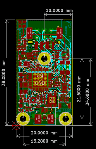 The SZP board is only 38x20mm and mounts with 3x M2 fasteners
The number of points that can be scanned is limited only by the maximum mesh size of the Duet 3 mainboard: 441 on Mini 5+ and 792 on a Duet 3 6HC and 6XD. Maximum scanning speed partly depends on the mechanics of your printer (no point in scanning so fast that whatever the scanning probe is mounted on is shifting in Z) and partly on the maximum speed that the sensor can be read. We are still experimenting with this but it is possible to scan 420 points in <12 seconds.
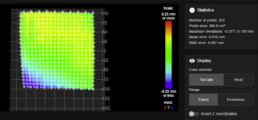 Example scan from a Voron Tridex (200x200mm bed) scanning from X-100 to X+100, and Y-100 to +90
Here is a video showing the scan
The integrated circuit that is used to provide this high speed scanning is used by most (all?) implementations of scanning probes. Where it is possible to optimise performance of the SZP is with the scanning coil itself. The next section will outline Duet3D’s R&D in this area.
Coil Design
The scanning process relies on a coil with appropriate inductive performance. This coil induces a magnetic field in the sensed surface and then measures that field. It is no surprise that the coil design is critical to the performance of the system as a whole. In general the larger the coil the more flexibility in terms of distance from coil to sensed surface, but lower resolution in differentiation of surface anomalies. Duet3D has tested coils with diameters: 10mm, 12mm, 15mm, and asymmetric coils (11x14mm). All these coil sizes can be used effectively, and research is ongoing as to the “optimal” coil diameter.
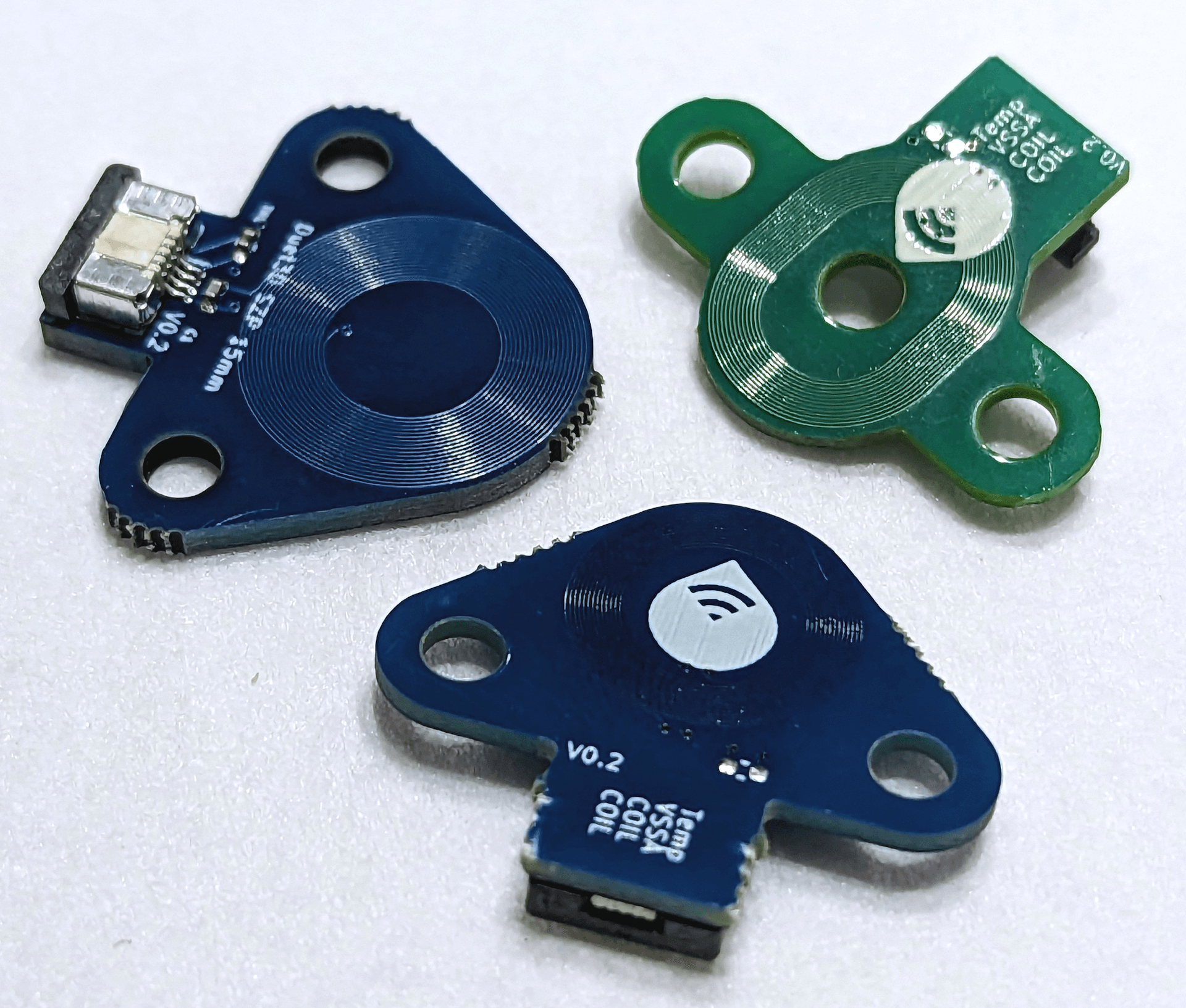 Different coil designs for the SZP
Different coils resonate at different frequencies, the frequency also changes depending on the distance from the metal bed. In general smaller coils, closer to the bed have higher theoretical resolution, however smaller coils also have shorter effective range, requiring more tuning to get right. RepRap Firmware from version 3.5 has built-in coil power tuning using GCode command M558.2. This is carried out as close to the bed as the coil will be used during a scan. Then RepRap firmware will scan through a range of heights to calibrate the height vs the coil output. Because this is temperature dependent we are currently recommending doing this before each bed scan (calibration takes a couple of seconds). As we characterise the performance of the coils over temperature better, it may be possible to use the built in thermistor on the coil to remove this calibration step.
 12mm multilayer coil
 15mm two layer coil
 Experimental oval shaped coil, designed to be mounted under a BL touch, so the pin can deploy and retract through the hole in the middle
Limitations
It's important to understand the limitations of any solution, we covered some of them in our previous blog post, and here are some of the key points:
Temperature dependent performance is a known issue with inductive sensing and this design is no different. As its very quick to calibrate this is not an issue in practice, however we may remove it entirely using the built in thermistor in the future
With a magnetic bed with strong point magnets set into the bed it is possible that these magnets can disturb the probe readings. This does depend on the bed surface. To emphasise the issue here is a scan of a magnetic bed of this type with the flexible sheet removed:
 Scan of a magnetic bed with the flexible sheet removed, clearly showing 9 of the magnets
In practice the flexible sheet over the magnets removes this issue in most cases.
There are other options for scanning that we are experimenting with, including using the IR sensor, or a laser based distance sensor, however both of these depend on the bed’s reflective properties.
Other Uses
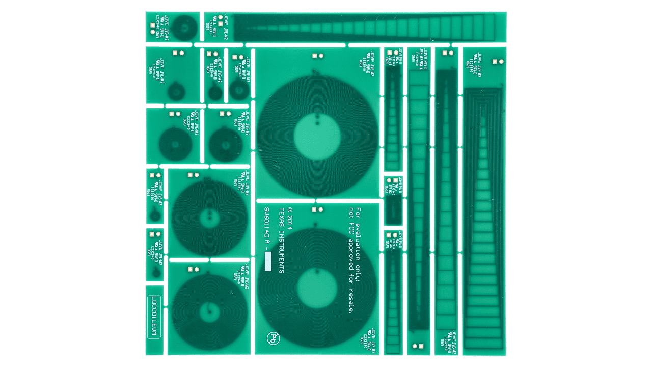
Scanning the bed quickly so bed surfaces can be swapped with impunity is a great use for this technology! However, this is Duet3D so we are looking at other uses for this technology as well. Inspired by the TI reference coil design:
 (image from TI.com “DCCOILEVM Reference Coil Board Evaluation Module top board”)
This shows examples of very directional coils, so we are considering other uses for inductive scanning sensing including:
- Using a coil or coils to sense a nozzle and determine nozzle XYZ offset. Non contact nozzle position sensing in 3 dimensions will be very helpful for tool changing printers. Current solutions rely on optical image processing, electric contact or physically triggering a switch, all of these can be disturbed by filament residue on the nozzle.
- Using a higher resolution coil to scan a metal filament print for in process inspection. The original use of this inductive eddy current technology was in non-destructive testing: the ability to look “inside” the surface of metal parts to detect cracks and voids. There may well be the opportunity to use this process to characterise the output when printing metallic parts.
Documentation for the Scanning Z Probe can be found here:
