Duet3D Research – Defect Detection
The latest generation of Duet3D control boards: the Duet3 family, come with single board computer integration – they can be attached to a Raspberry Pi (or your preferred SBC). Much of the Duet 3 controller’s functioning can be controlled and monitored from the SBC through an API (C#, Python), making it relatively easy to integrate Duet 3 controllers with other applications and peripherals on the SBC. One such possibility is interfacing with a camera. There are lots of uses for this configuration, from gathering data that can be used to improve tuning and procedures, to producing timelapses for YouTube videos. In future posts we will be looking at some of these use cases.
Stepping back a number of years to the early days of this integration (2018), we were investigating using cameras to detect print defects. This was our initial foray into visual “In Process Monitoring”. The idea was that we could use a camera and some basic machine vision to detect print errors and alert the user in case they wish to intervene. This is certainly something that works in principle – as we will illustrate – but it is perhaps not very practical in the form that it was implemented in at the time. This idea has evolved into the techniques we are now using for research, and we will be discussing that in forthcoming posts. We’ve decided to start these blogs here as it is where we started.
Prior to us conducting this research there were already examples of imaging in 3d printer quality assessment (very non exhaustive list: 1, 2, 3, 4). At the time we wanted to try something different: deliberately image each layer and extract as much information about that specific layer as possible. This aim led to decisions about camera mounting and error detection.
Camera Mounting
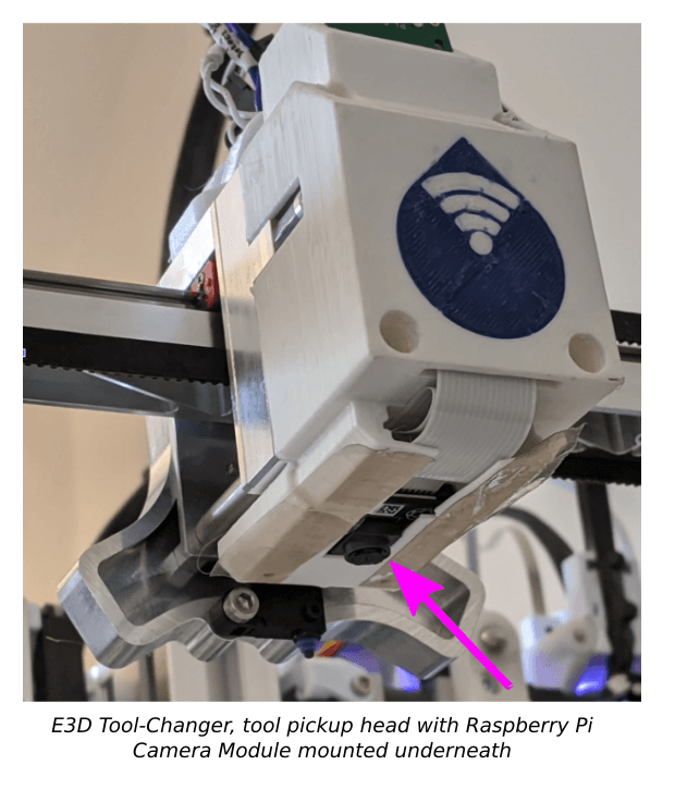
We initially used a camera mounted on the tool pickup head, the other options are to have one on an individual tool, one mounted close to the nozzle or to mount one in a fixed location. There are various advantages and disadvantages to doing this, some of which were hard to weigh up without testing it practically:
Pros:
- Smaller form factor: you don’t need the camera to be stood off at a distance from the bed, and it can work in printer geometries where a clear view from a fixed location might be difficult or impossible.
- Greater detail available by combining multiple images, a cheap camera can get a lot of detail.
- The camera is always focused at the point of interest, and perspective transforms are not necessary. (To get an idea about perspective transforms see figure 3 in this paper by Jeremy Straub).
Cons:
- Slow to image: the camera must come to a complete stop between images or at least move slow enough not to have motion blur. An expensive camera with high sensitivity can be used to allow for faster imaging but it will still be slower than imaging the whole print bed in one image. This is probably the biggest factor affecting its practicality.
- Individual images must be registered correctly, and matched in other ways (such as luminance).
Using this camera we take a series of photos, covering a grid over each layer. These are stitched together to get a high resolution image of the entire print:
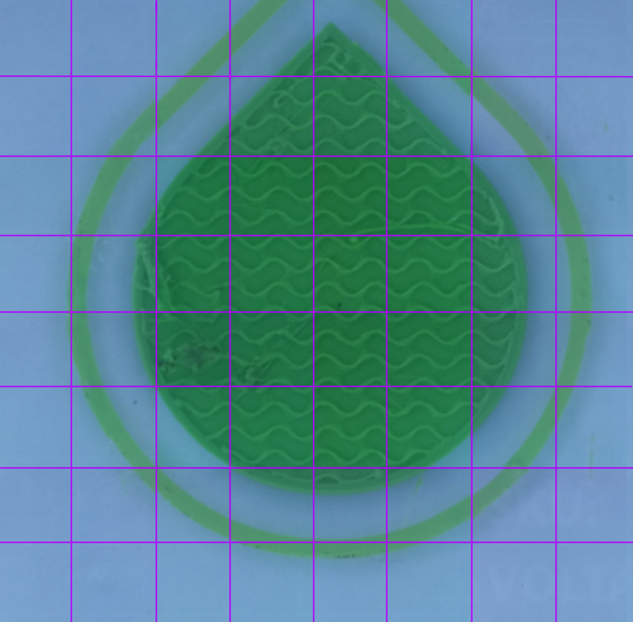 Image of a layer of a 3d print taken in multiple segments, with the segment lines highlighted.
Approach to Detection
It is quite typical of specialised machine vision tasks that a simple approach will produce the right output in the majority of cases, but the amount of work needed to go from the majority, to nearly all, and from nearly all cases to every case is huge. This is because to perform really well, the system needs to know about and understand a lot about what is happening: what really is a defect? This kind of understanding is typically achieved using machine learning techniques, and these require a lot of data. This data set has to be relatively large and representative of real world defects, and would probably need to be manually tagged. Whilst this is something that can be achieved in the future, our goal was to see if the process could be made to work well in principle first.
The approach here therefore, was to use simple machine vision approaches. It does work reasonably well, and it only requires the gcode to work. Here we will use a deliberately sloppy print as an example.
Detecting Errors
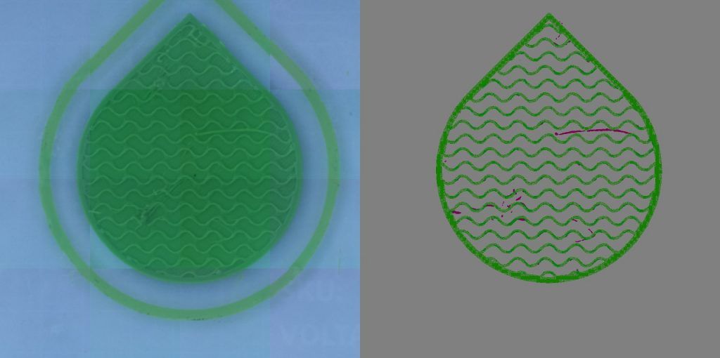
The first stage of defect detection is to find all the changes between images of sequential layers. The image below shows the layer 6, 7 and their difference, left to right. This difference was only registered in the green areas of the image.
 From left to right (1) a layer of a 3d print, (2) the following layer, (3) a black and white representation of the changes between the two images
There are four kinds of feature in this difference image
- There is a background
- There are deliberately printed tracks
- There is “stringing” on the right hand side
- There is an artefact caused by a defect on the previous layer that has continued to this on the left.
This can then be compared to what is predicted based on an image created by drawing the g-code instructions for each layer into an image (right).
 (1) the changes from the previous figure and (2) a visualisation of the gcode for that layer
The comparison can then be rendered into a composite image showing where they differ, and where they are the same (below). If an alert system is desired, one could detect any region that is above a specified threshold.
 (1) The 3d printed object at a specific layer (2) a visualisation of the top layer showing areas where the system detects incorrect printing
The rest of the print (most of it) is shown below. It is clear that this process performs well. However, it works on the basis of looking for changes where there shouldn’t be, and does not have any deeper understanding. This means any kind of deviation can be picked up, but there is no method for classifying changes into important and unimportant. In addition pixels belonging to a defect that occurs in a place that should be printed on in the current layer, cannot be picked up. This is apparent in layer 9 below, where the fist full layer over the infill obscures the blob in the centre of the image.
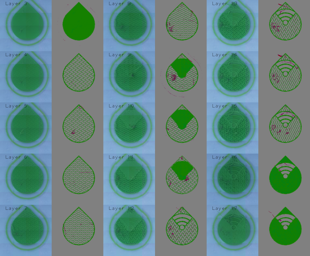 A composite image of layers 3 to layer 17 of the printed part, showing the detected errors in each image.
But is it practical?
The main obstacle is the time it takes to get good images, we were surprised at how slow we had to run the imaging to get decent pictures: significantly more time was taken with imaging than printing, we could either move the head constantly, but slowly, so as to decrease motion blur, or, we could stop. Stopping, however, is also time consuming as the deceleration introduces vibrations that must be given time to die out. This may be practical for certain specialised applications where any defects internal to a print are unacceptable, but for the majority of FDM prints the imaging time was prohibitive.
The two improvements that would make this useful would be (1) using one or more fixed cameras or (2) a better camera, with a fast shutter time and a flash. With these overcome, a basic defect warning system could be introduced along the lines of this implementation. This could provide a start point (and perhaps motivation) for people to gather data for more accurate warning systems based on machine learning in the future.
As already mentioned there are projects like the spaghetti detective using a fixed camera to detect a failed print with a machine learning approach.
Since doing this work we have taken the tool changer mounted camera in a very different direction, using it to get precise measurements of the properties of single tracks of extrusions. This has proven quite useful for gathering data on performance, and is part of what we will explore in upcoming posts.